| James S. and Susan W. Aber |
|
| James S. and Susan W. Aber |
In the late 1990s, we began working with Brooks Leffler, who custom-built some of our early radio-controlled rigs, and during the KAPiCA06 conference we constructed a KAP rig under his guidance. Since then, we have built and rebuilt numerous KAP rigs. Meanwhile, Brooks Leffler's kits and techniques have become the KAP standard worldwide. Brooks retired from commercial activity in 2013, and now Ken Conrad carries on the tradition at Great Winds Kites in Seattle—see brooxes.com.
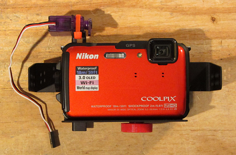
| Camera cradle with micro-servo on post to trigger the shutter button. Because this camera is waterproof, there is no external socket for electronic shutter control. Note the large red tripod mounting screw. The position of the mounting screw is critical for balancing the camera in the rig and placement of other components. | ||
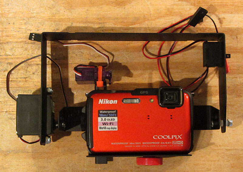
| Main frame with tilt servo (lower left) and power switch (upper right). During a crash, one of the most likely things to break is the connection between the tilt servo and the camera cradle. This is reinforced with extra screws, and we have a spare servo for potential replacement. | ||
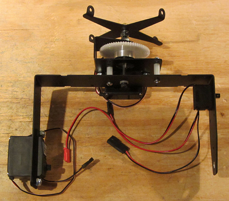
| Pan servo (back side), pan gearing, and Picavet cross (top) assembled to the main frame. Locking washers and lock-tight glue are used to fasten the Picavet cross securely to the main gear axle. | ||
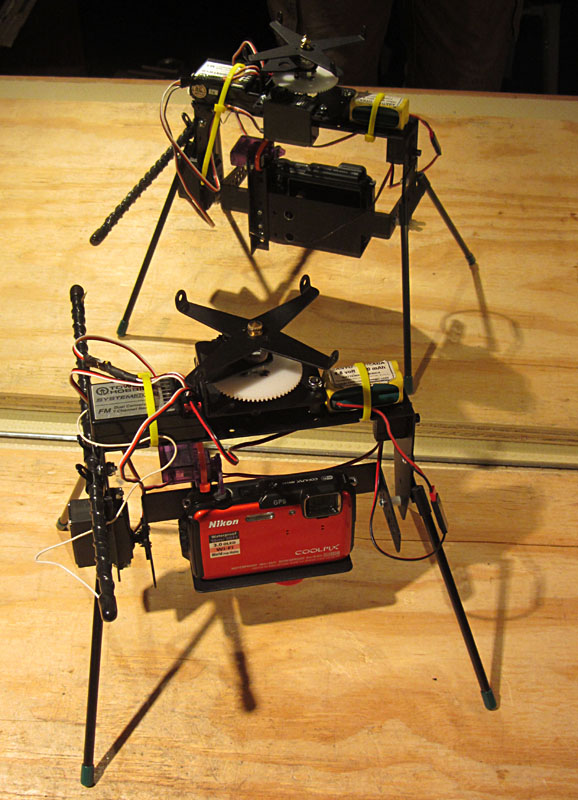
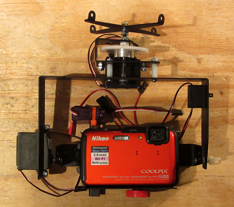
Complete frame standing on legs with radio receiver and antenna (left) and battery pack (right). Mirror view shows backside of rig. All wiring is loosely connected at this stage for testing servo action and camera movement. During a crash, the antenna is likely to pop off and the wire break. Note antenna wire (white) is looped under the zip-tie around the receiver. | 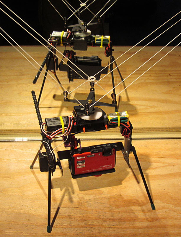
Final assembly with Picavet suspension. Mirror view shows backside of rig. All wiring is tucked in and secured with zip-ties, so there are no loose ends to get tangled. Note how antenna points backward, so it would not appear in wide-angle shots. The legs would not be attached during flight for the same reason. | |
![]() Return to KAP camera rigs or KapHome.
Return to KAP camera rigs or KapHome.
All text and images © by the authors.
Last update Jan. 2014.